
‘Time marches on’!
When I received my full call (now known as an advanced licence) in May 1977 I was given the call-sign, VK3BJE. It is now interesting, in my autumnal years, to reflect on what it was like being a radio amateur in the 1970’s. Single-sideband suppressed carrier (SSB) was the popular voice mode. It was a very efficient derivative of amplitude modulation (AM), the now legacy voice mode, and SSB began to make inroads into the hobby. While commercial transceivers, designed for amateurs, could be purchased in Australia from Dick Smith Electronics and others (Japanese and US manufacturers) many amateurs made their own transmitters including SSB equipment. Home built receivers were widely used as well. Wireless telegraphy skills were also required of those seeking a full call. You had to be able to send and receive morse code transmissions in plain language at ten words a minute. Morse code (CW) transmissions were popular and some amateurs never made voice contacts and were proud to tell amateurs of their skills. Other amateurs found the morse code requirement too great a barrier and were awarded a limited licence and were thus confined to the VHF and UHF bands..
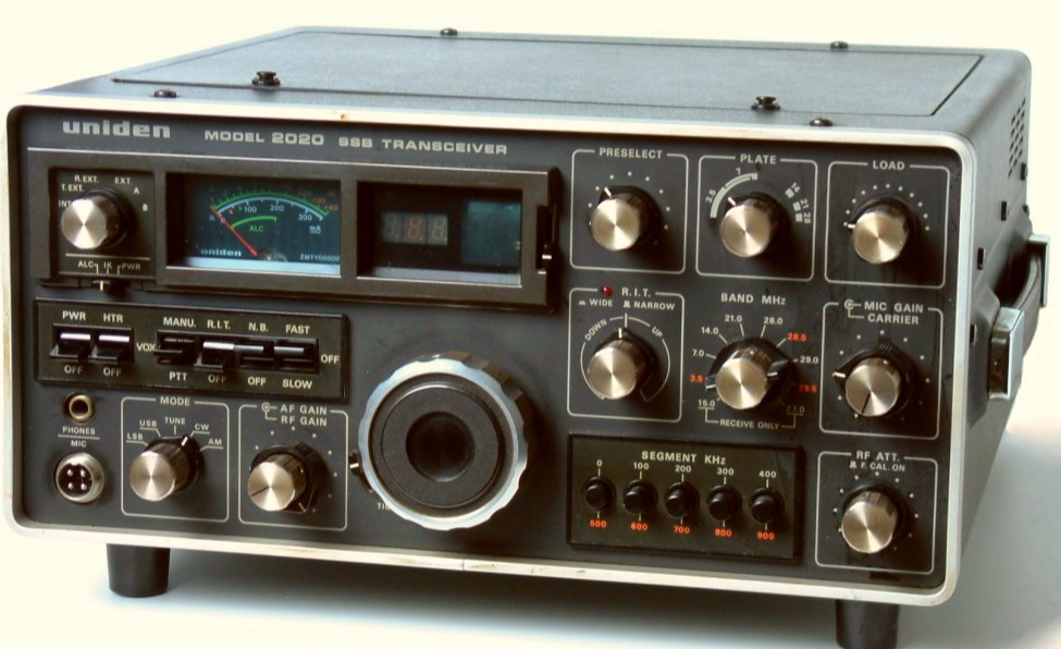
There were three commonly available Japanese transceivers (high frequency, HF) on sale when I obtained my licence. The Yaesu FT101 competed with Kenwood’s TS520 and the new kid on the block was the Uniden 2020. In 1977 I ordered a Uniden 2020 from Vicom Pty Ltd (Peter Williams, VK3IZ) and kept my radio in mint condition until the 2000s when I sold it.
It was no sooner out the door that I regretted the sale! These three radios were very popular with Australian amateurs. and they were all very good performers. These three radios had a price advantage for purchasers as US equipment was more expensive.
I have kept all of my logbooks and I enjoyed hundreds of contacts with my Uniden 2020. Band conditions in the late 1970s and early 80s were very good and I had many DX contacts.
These three radios were equipped with five bands: 80, 40, 20, 15 and 10 metres and WWV/H as can be seen on the Uniden’s band switch centre right. One hundred and sixty metres (160m) was not usually provided in amateur transceivers, certainly not the Uniden and the Kenwood and began to appear during the late 1980s and 1990s. At the World Administrative Radio Conference in 1979 at Geneva (WARC 1979), the International Telecommunications Union, granted amateurs additional bands within the HF spectrum: 30, 17 and 12 metres. These were narrow bands and allocated to full call amateurs by the Australian regulator. These new allocations were soon included in new transceivers along with the 160 metre band. I have made quite a bit of use of 30 metres (SSB, FT8 and CW) and also 17 with the SSB and FT8.
If one wanted to try out 160 metres, then our only medium frequency band, you had to either convert a commercial transmitter or transceiver or build a dedicated 160 metre rig. I did both.
For this post I have drawn upon a paper I gave to the South Coast Amateur Radio Club in Adelaide in 1993. If you would like a copy of the paper (20 pages and lots of references) please email me. I am in the process of downsizing and have been giving away (eg the taxi radio on 53.1 AM) and selling items I no longer need as I aim for a more stream-lined shack and smaller footprint. All of the equipment I describe in this blog post is to be given to an amateur who has expressed interest in the 160m band and home-brewed equipment. But, before it goes, I thought I should photograph all of the gear and write a post as a memory from those times.
AWA Forestphone
I used to listen to the coffee break net in Melbourne. I really liked listening to these amateurs. Their signals were generally strong and clear and many took great pride in achieving quality audio in the permitted bandwidth within the 160 metre band. I have my original licence dated 18th April 1977 and the 160 metre band extended from 1800 Hhz to 1860 KHz (now 1800 to 1875 KHz). Some of the stations used the AWA Forestphone.
So I searched around for an AWA Forestphone. This radio was a single channel medium frequency (MF) solid state unit used by the Victorian Forest Commission and became popular with amateurs when sold off by the Government as VHF FM radios were introduced. I cannot remember where I purchased mine. I paid $90 for it which I thought was a bit expensive but I got more that $90 fun from this radio in both Victoria and South Australia. Cosmetically it was reasonable given the hard life they had in forestry vehicles. The power output metre was not working in mine and I replaced that and retuned the radio for the 160 metre band. The radio was originally on a higher frequency, around two (2) MHz. To bring it down to 1820 KHz required adding some additional low value capacitance across the coils. I used 100pf silver mica capacitors. It tuned up beautifully and from memory, put out about five watts. The frequency control was achieved by a crystal oscillator and I purchased a 1.825 MHz crystal to get it onto the coffee break channel. In South Australia we later moved frequency to 1.843 MHz as cheap disposal crystals came on the market. The net now works on 1.857 MHz on Thursday evenings but this change was made after we moved to the Adelaide Hills in 2003 and I stopped using 160 metres. My Forestphone worked beautifully but I eventually swapped it for a VHF low band taxi radio which had been converted to the six metre band AM frequency of 53.1 MHz. The swap occurred after I had built my own 160m transmitter.
160 metre home brew transmitter
The transmitter is built into a steel and aluminum case. The photo shows the front panel: on and off switch (redundant), a carrier switch for am/cw and plate and load capacitors. On the rear panel is a rotary switch to change channels. Five crystals are visible in the photo below. The tank coil is wound around, you guessed correctly, a 35mm film container. Additional fixed capacitance is added to the load capacitor to ensure it has sufficient capacity for 160m.
My transmitter is built around a 6GV8 triode/pentode. The 6GV8 was made in Australia by AWV Pty Ltd for use in monochrome television sets. The high mu triode was a sync amplifier and the pentode a wide band video amplifier. The valve is rugged and in a simple transmitter will only work as required, usually just for a few hours per week, intermittent amateur and commercial service (ICAS). The bleed resistor and radio frequency choke are just visible near the load capacitor. This ensures that the high tension voltage (DC) is bled (leaked) away to earth for safety reasons when the transmitter is turned off. A socket for connecting a morse key is located on the rear of the case. The 6GV8 valve is mounted via a valve socket attached to a piece of printed circuit board. It is on the left hand side of the photo and is mounted horizontally.
As shown above the transmitter is for CW only. To make this transmitter work on AM you need a modulator and I will describe the approaches I took.
Transmitter Power Supply
I built the power supply for the transmitter in a re-cycled aluminium and steel box. I used some printed circuit board to cover up some holes on the front panel and the painted the copper with aluminium.
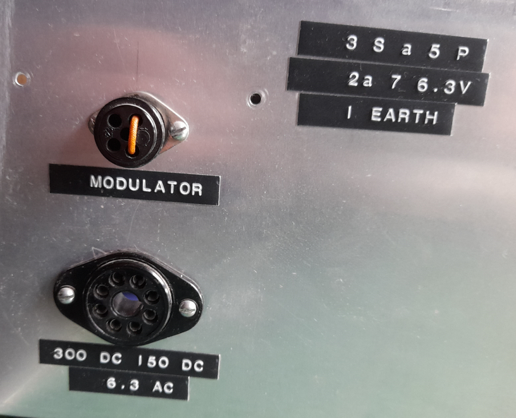
The rear panel of the power supply shows the DC power out through an octal socket with the voltages marked: 300 and 150 volts DC and 6.3 AC for the valve filament. The link covered with yellow spaghetti completes the plate circuit when the transmitter is in CW mode and when removed and the modulator plugged in, the AM mode is ready. I thought the arrangement for the modulator connection was pretty neat! The figures at the top right are the octal socket connections.
Valve Modulator
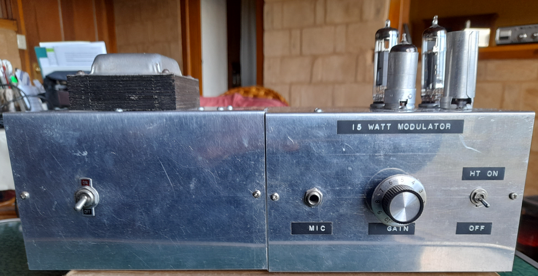
I chose first up to build a valve modulator. The circuit I used is from the Radio Communication Handbook, Fifth Edition, Volume One, RSGB, 1977. The photo below shows my modulator which is build on and in two aluminium boxes joined together at one end. The left hand box contains the solid state power supply and the modulator (a special audio amplifier) is built on and in the right hand end.
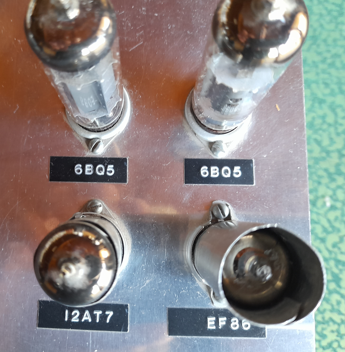
Top view of valve placement

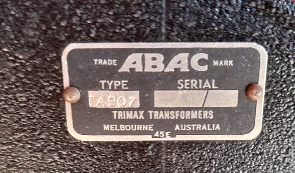
The modulator is designed to produce up to 15 watts of audio depending upon the transformer voltage, which is more than enough to modulate my transmitter to 100%. The circuit is simple. The EF86 provides the microphone amplification which is fed to the phase splitter (12AT7) which then drives the two amplifier tubes in push-pull AB1 mode. In the early 1980s I was fortunate to be given a Trimax ABAC model TA907 modulation transformer. So the audio was coupled to the transmitter via the modulation transformer as per the circuit diagram.
The other transformer winding is coupled into the plate circuit enabling high level modulation. Amplitude modulation occurs when a radio frequency carrier wave is used for the carriage of speech by varying the amplitude of the wave in harmony with the audio (speech) waveform. I commend the excellent chapter from the RSGB Handbook for anyone wanting to learn more about AM.
To be continued in Part 2
