In this section I will discuss the solid state modulator, matching it to the transmitter and the electronic send and receive switch. I will also discuss receivers I have used for 160 metres.
I was pleased with the valve transmitter and modulator and enjoyed many contacts with just seven watts of radio frequency into a quarter wave long wire cut for 1820 KHz. Matching was achieved with a home brew L match coupler. However, I kept meeting on air amateurs who were able to operate with more power, in one case 30 watts from a home brew rig. It takes a different range of components to go from seven watts to 30 watts! I even worked Bob, then VK3ZL, in south western Victoria. Bob is now deceased and my qso with Bob was the longest distance I made with seven watts.
Finding bigger power transformers, valves that could handle more power, stronger chassis construction and space in the shack all become significant. There was one disposal shop in suburban Adelaide and I had picked over the transformers and purchased quite a few and there were no high voltage high current ones left in stock. Tuning gangs were also sought and often purchased from buy and sell events, ham fests and similar. I had in mind perhaps going solid state and building a 60 watt modulator which would provide experience and the drive to design a solid state transmitter for about 30 watts. How would I design and build a modulator and how would I match a low impedance output from the modulator (8 ohms) to a high voltage high impedance tank circuit in a valve transmitter? I was also seeking decent, high level modulation: not the thin audio in AM from commercial transceivers! The other comment worth making is that I am and was an amateur: radio is a hobby. I was also very busy at work. Radio helped me manage difficult work events because it demanded total concentration, especially playing with mains voltages and higher.
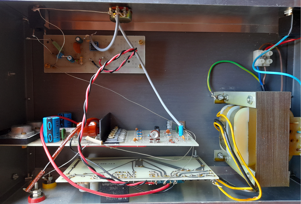
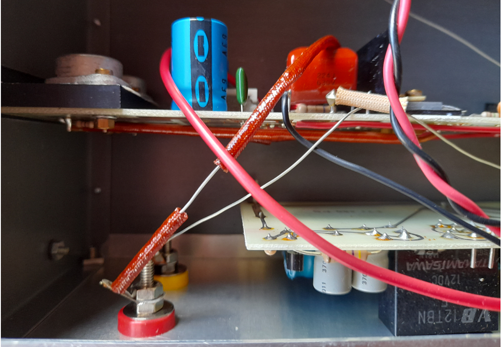
So after some thinking and reflection and speaking with amateur friends who were playing in the 160 metre playpen, or sandpit or national park I decided to build a kit amplifier and power supply and take the plunge! I like to think of our amateur bands as national parks. It is not a perfect metaphor but does convey something of the wonder of experimenting and building, problem solving, adventure and hopefully success. I chose an amplifier kit from one of electronic dealers. It provided all the components that were required as per the circuit description. ‘The assembly manual (AEM, July 1985) describes the power amplifier module as a “high performance general purpose unit intended for use in a side variety of applications’ (Dawes, 1993, p.14). The assembly manual gives full circuit details and operating conditions and suggested power supply arrangements. The circuit needs both positive and negative voltages of 40 and 15 volts and I built the ‘480 power supply kit’ which is capable of powering a 100 watt audio module or two 50 watt modules. Thus my arrangement has plenty of head room and coasts along with power in reserve. The photo below shows the fairly heavy power transformer which supplies 56 volts at two amperes from the secondary winding. The amplifier kit was easy to construct and the setting up procedure reasonably straightforward, the main task being to adjust the quiescent current to about 100 milliamperes which ensures that the output mosfets operate with a negative current coefficient establishing a stable operating point. The microphone pre-amplifier circuit is my design and it works satisfactorily. It needs a bit more gain with some microphones. The three photos below show various views of the amplifier board, power supply circuitry and the power transformer. The microphone amplifier is the small board shown in the top left hand corner in the second photo.
Matching the solid state modulator to the transmitter
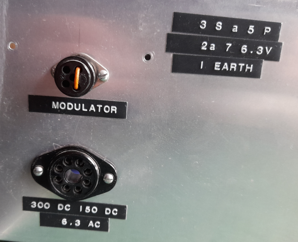
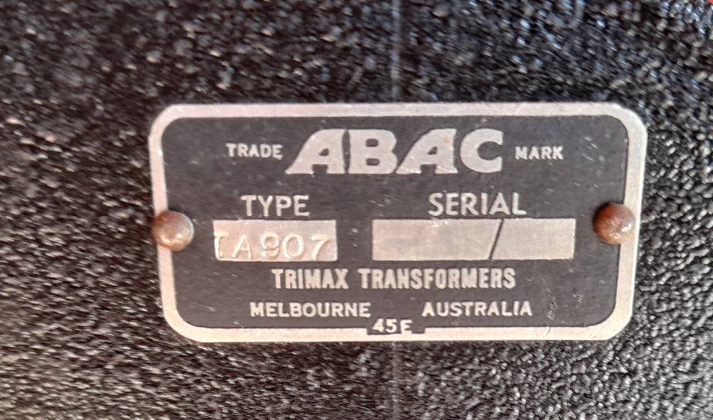
The eight ohm impedance output of the mosfet devices is fed into the eight ohm secondary of an audio transformer and the high impedance primary (8000 ohms) is wired in series with the plate circuit of the transmitter. The same connectors are used. as for the valve modulator. This is a standard configuration and is described in both the RSGB and ARRL handbooks. The audio transformer is heavy duty and rated at 12 watts.
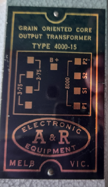
I purchased two of these transformers from the the Adelaide Hills Amateur Radio Society’s buy and sell. These audio transformers were commonly available in the last days of valve hi fi equipment before the newer renaissance of valve audio equipment once again available in the hi fi market place. My transformer is described as ultra-linear and has a number of taps and plenty of iron to ensure that the audio output is smooth without peaks. This quality I thought was just what I wanted from a modulator! Taps in both the primary and secondary assist in finding the right impedances in the circuit, especially in the high voltage plate circuit. It is important that the best impedance matching is obtained to ensure 100% modulation.
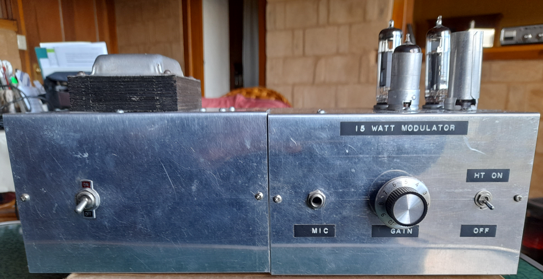
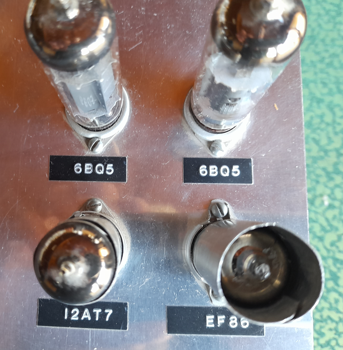
The modulator works well. In any fine tuning of the modulator a new microphone pre-amplifier circuit with a bit more gain would improve the set up. A solid state equivalent of the EF86 is needed?
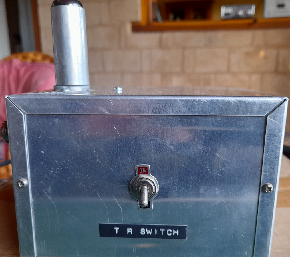
Electronic Transmit/Receive Switch
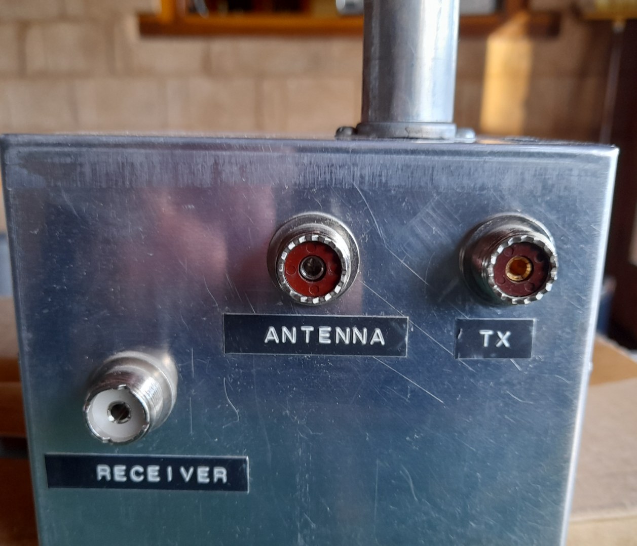
How do you switch an antenna from the transmitter to a receiver when using separate appliances and not a transceiver? The most common way of switching the antenna from receiver to transmitter is through the use of a relay. Activating the push-to-talk switch on the microphone, switches power to a relay in turn switching the antenna to the transmitter. When the switch is released, power stops flowing and the relay lets go, thus switching the antenna to the receiver, that is, the ‘default’ position. The advantage of this system is that it is in common use, relays are cheap and if you use an industry four-pin arrangement for the microphone connector you can experiment with other microphones made for entertainment (dynamic) and recording and broadcast use (condenser).
An alternative arrangement, which is very fast and has more in common with modern diode switching is an electronic transmit-receive switch. If you obtain my 1993 paper there are references relevant to this topic. The circuit I have experimented with comes from Grammar (1971, pp. 220 – 222) The circuit used a 6AH6 wired as a triode. I did not have one of those so I used half a 12BH7A, which is a double medium mu triode. There was a shop in the Adelaide suburb of Norwood which had valves for sale and I saw this valve for a very small price and I bought two. I did not have a circuit in mind at that time but I knew what the valve was and I would probably use it one day. This valve was developed as a vertical deflection amplifier in monochrome television sets, is rugged and works very well as an electronic transmit-receive switch. The valve is similar to 6CG7, 12AU7, ECC82 and they have found a place in the audio world as well and checking out the prices on the www almost dislodged me from my chair! Other T-R circuits can be found in the ARRL (1962, pp. 252 – 253) and ARRL 1988 (1987, pp. 19-7 – 19.9).
Checking the operating parameters for this valve (Miniwatt, 7th Edition, 1962, p. 76) shows that with a filament voltage of 6.3 volts the current draw is 600 milliamps. If you look carefully at the photo below you will see two small transformers mounted at right angles to each other. The one at the bottom is a 6.3 volts 1.2 amps filament transformer. It provides the 6.3 volts for the filament as well as well as applying 6.3 volts to the 12 volt secondary of a second transformer which gives about 150 volts across the primary, that is, the second transformer is wired back-to-front. I used a transformer designated M-2155 which has a one ampere secondary winding which is more than adequate for the purpose. If your eye sight is reasonable you will see that the transformer came from Dick Smith Electronics and was therefore a new item. I then rectified and filtered the output and the resulting direct current finishes up as a good 150 volts for the plate of the T-R valve. The 12BH7A plate is rated for normal use at 250 volts (Miniwatt, 7th Edition, 1962, p. 76). The valve is acting as a switch and is run well within its rated capacity. The wiring is point to point using one tag strip and the various connectors.
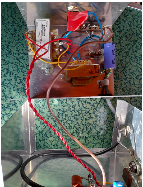
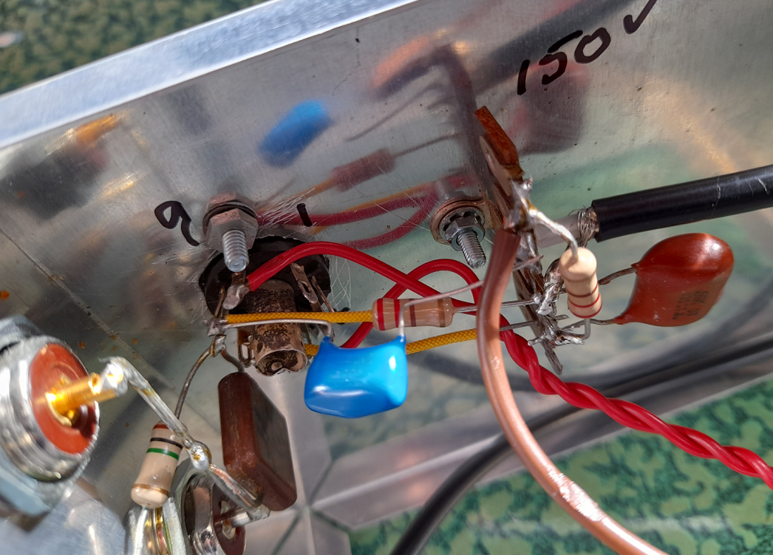
You need to be aware that one negative feature of an electronic T[R switch is that such a device can generate harmonics. It is recommended that an additional coupling circuit be used between the transmitter and the antenna even if you are using a resonant antenna. I built an L coupler (Dawes, 1991). As well the pi-coupler output circuit in the transmitter assists in minimising harmonics. I strongly recommend that the electronic T-R switch be built as an outboard device on its own chassis ensuring that is fully shielded and the valve should be shielded as well.
High Frequency Receivers
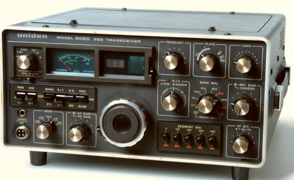
I was very interested to read Ray Robinson’s article called Retro Review: DX160 Receiver from Amateur Radio Magazine, Vol. 89, No. 3, pp. 34-37. I ordered this receiver on the 15th March 1975, the day our first son was born. I purchased it from the Tandy store at Rosanna, the suburb adjacent to Greensborough where I lived. Hitherto my receivers were old dual wave broadcast sets, home brewed regenerative and direct conversion sets and one unsuccessful attempt at a four valve superhetrodyne. The problem for me with home brewed receivers was always a mechanical one. And for many years reduction drives were unobtainable. How do you obtain an accurate frequency readout or know you are listening to the same frequency spot two days in a row? I know it could be done by people with engineering skills and good workshops but another factor, on reflection, is that we have now become used to more sophisticated and accurate frequency generation and readouts. We are looking back through a current lens. Perhaps our expectations then were lower? It is a bit like cars. Who would buy a car without a heater and no air-conditioning? Well in the 1960s and early 1970s cars for workers were purchased by the Victorian Government without heaters. Driving from Melbourne to Bendigo in the middle of winter was a bit of an endurance test and demisting windows had to be done by hand. Jeremy Bentham’s principle of lesser eligibility at work! Ray Robinson’s conclusion is that the Tandy DX160 ‘.. is a good entry level receiver’. I enjoyed mine. It was like a breath fresh air and the tuning, at least on the lower broadcast bands and 80 and 40 amateur bands, was quite good. After gaining my licence I eventually used the receiver for 160 metres and it was excellent in this role. At the time of writing my 1993 paper the only part of my 160 metre station that was not home brewed was my Drake model R-4C, which I purchased second hand. This receiver was just amazing and the filtering was excellent. Drake twins, the transmitters and receivers can still be heard on the various ‘boat anchor’ nets around the country .
Conclusion
What am I doing writing about a late modern project in a post modern world? I built my 160m transmitter in the late 1980s, a decade after we celebrated Captain James Cook’s ‘discovery’ of Australia, colour television was about eight years old and analogue, during the 20th century, in the last decade of the ‘cold war’ and when it was commonly thought, or perhaps just hoped, that we were on a linear trajectory towards a more civilised state of being.
Philips had a shop in Flinders Street Adelaide and I remember buying valves from the shop. The shop disappeared in the mid 1980s. I never saw valves being made but Philips did make them in Adelaide in their factory in the western suburbs at Hendon. I have, however, seen transistors being made. In 1986 I visited a factory in Shandong Province, China. The factory was within a prison and prisoners were making the devices. I looked from behind a glass screen so could not see the ‘doping’ process. The devices looked like 2N3055s. I had to change into special clothes to enter the dust proof environment.
So what was and is the value of building a small 160m transmitter? Well most of the components I used are recycled and if not used would probably become land-fill: that may be just acceptable in a modern world but definitely not in a post-modern one. There is no adequate word in English to describe how I feel about some of the components and the finished projects. Love – is not appropriate! Love in English has about three meanings derived from the Greek words philos, eros and agape. You can look these up in a dictionary or on line. Philos is the closest but it is still inappropriate. Sisterly or brotherly love or the feelings that motivate carers and human service professionals who speak of a vocation is not appropriate. But like does not work either. All I can say is I have a fondness for this gear and the bits and pieces I collected over the years. Some of the condensers, I mean tuning gangs, go back to my boyhood days in Devonport and building crystal sets and one/two and three valve regenerative receivers. I could say, then, all of this gear has a meaning attached to other amateurs and the relationships I have enjoyed over the years.
As well there is the learning associated with building the gear. Developing an understanding of circuits and their constituent parts, their roles and how they work and how to manage working with potentially lethal voltages was very important. There were only minimal requirements for sheet metal work. All my boxes were premade. I had to drill holes and make cut-outs for transformers. But I did learn some basic metal work skills at high school.
The role of broadcast radio was important. Radio plays a different role today where there are so any ways of getting news, real and fake. In the 20th century, particularly before 1956 and the start of television in Australia: Sydney and Melbourne for the Olympic Games, radio competed with the newspapers and in Tasmania the news on 7NT was 15 minutes long and rural and social reporting was very important for isolated communities. Commercial stations also played an important role in local communities and there was very little networking then in commercial radio. Local radio was indeed local radio. And people knew that there were ‘hams’, people with big and different antennas who played with radio.
Then there was and is the individual development of personal skills. I strongly believe in and practice life-long learning. I did not want to spend my life doing the same things each year ad nauseaum. I did not want 20 years of experience to be 20 multiplied by one. Amateur radio has so many facets, highways and byways, it is impossible to be bored. And there are some activities I have never tried: moon-bounce or more correctly communications using the moon as a passive reflector, fox-hunting or more correctly finding hidden transmitters or amateur radio direction-finding and using satellites and communicating with the International Space Station.
I will not be building any more projects: with a tremor in my hand and poorer eye-sight close in, it is almost time to lay down my soldering iron – but not quite! I did solder an OLED screen to an MMDVM board recently and bridged two of the four tabs. An inspection of my work with the magnifying glass before putting the hotspot into service allowed me to quickly remove the bridge and all was well.
I hope you enjoy reading these reflections and perhaps consider taking up a hot soldering iron!
References
480 Power Supply, K 3438, 1976, Assembly Manual for the 480 Power Supply, Electronics Today International, December 1976.
60 watt Mosfet Amp, Module K3441, Assembly Manual for the 60 w Mosfet Amp, Australian Electronics Monthly, July 1985
Dawes, J., 1991, A Simple Antenna Tuning Unit for all Bands, Lo-Key, March 1991, Issue No. 29, The Journal of the CW Operators Club.
Dawes, J., 1993, 160 Metre Homebrew Equipment, unpublished paper delivered at The South Australian Technical Symposium, South Coast Amateur Radio Club, Adelaide, Saturday 24th July 1993
Grammar, 1971, G., Understanding Amateur Radio, American Radio Relay League, Newington, Connecticut
Miniwatt Technical Data 1962: Valves, Picture Tubes and Semi-conductor Devices, 7th Edition, Philips Electrical Industries Pty Ltd, Artarmon, NSW
Robinson, Ray, 2021, ‘Retro Review; Realistic DX160 Receiver’, Amateur Radio Magazine, Vol. 89, No 3. 2021, pp. 34 – 37.